In this Chapter we present a step-by-step procedure to be taken as example to program the DT1260 (also named SciDK) unit using Sci-Compiler. More examples are given as diagrams in the Example Project folder of Sci-Compiler. It is possible to use them to move the first steps with the software and modify them to create custom design.
In the following we show how to create, load and test a firmware implementing waveform recording on both analog channels of the DT1260 with adjustable signal offset. Follow this procedure only after all the preliminary operations described in the installation section have been fulfilled.
-
Launch Sci-Compiler software
-
Click NewProject and select SciDK-DT1260 as a target for the project itself. Choose a name and folder for the project and press Create. A blank diagram page will open.
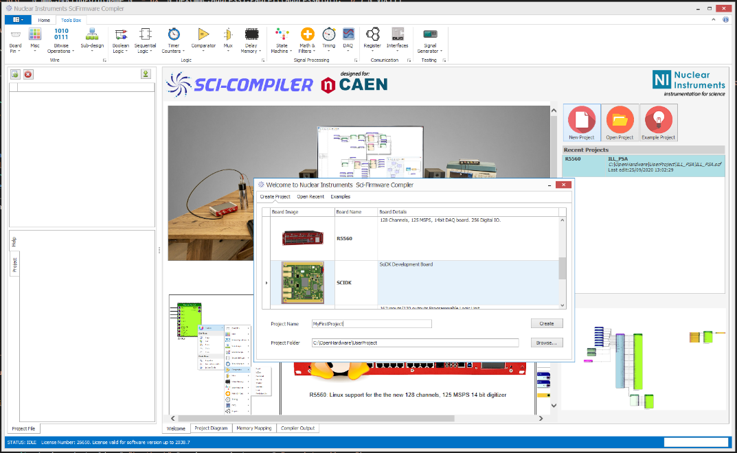
Figure 8.1: create a new project for DT1260 unit in Sci-Compiler
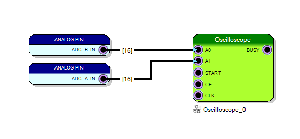
- From the top toolbar, pick Board Pin 🡪 Analog In block. The following window will open. Select both rows, corresponding to the two analog input channels of the DT1260 and Press Ok. You will see the two created blocks placed in the blank sheet.
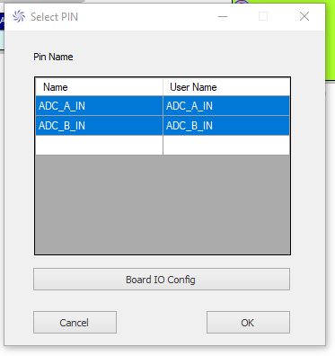
-
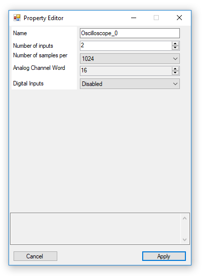
From the top toolbar, pick DAQ 🡪 Oscilloscope. The corresponding block will be added to the diagram
-
Right-click on the block and set the parameters as shown below, then press Apply
- Connect the blocks on the diagram as shown below.
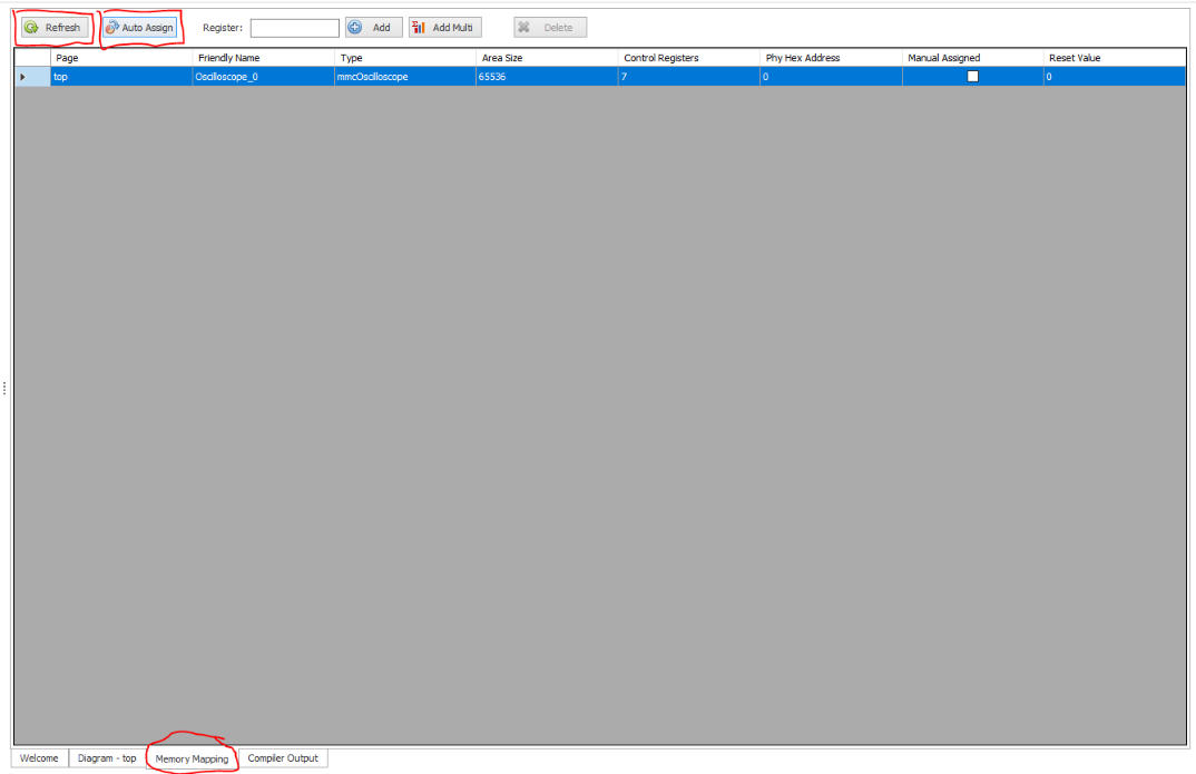
- Go to Memory Mapping tab and press first Refresh and then Auto Assign in order to assign the memory address of the oscilloscope.
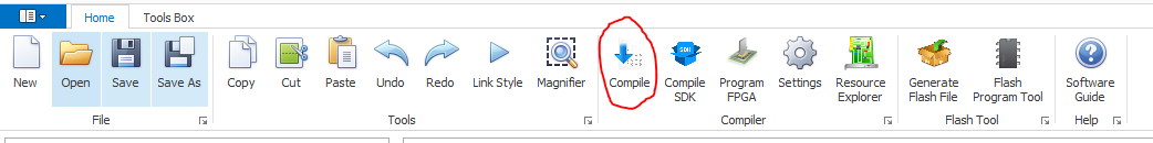
- In the top toolbar, go to Home 🡪 Compile
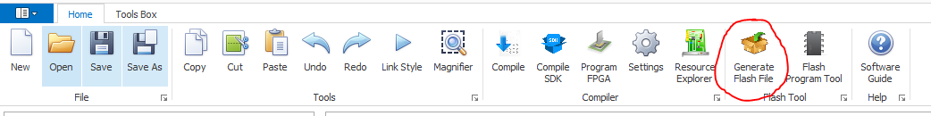
- After compilation processi is ended successful (see the results in the Compiler Output), click on Generate Flash File. A .niu firmware file will be generated and saved.
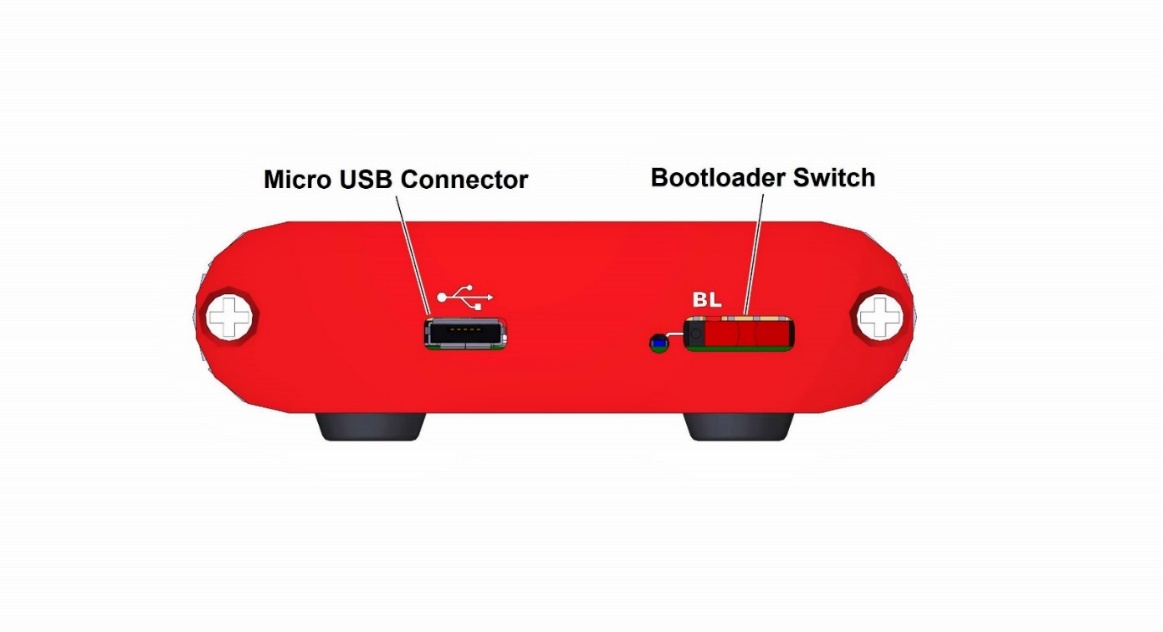
- Disconnect the DT1260 unit from USB and move the bootloader switch on the rear panel to the right. Power on the unit connecting the micro-USB cable to the PC. The BL LED should stay ON in blue.
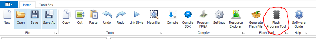
- From Sci-Compiler, press Flash Program Tool
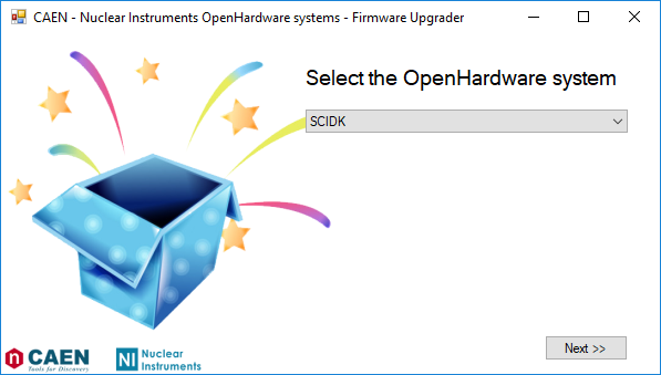
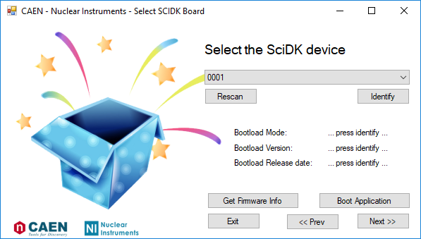
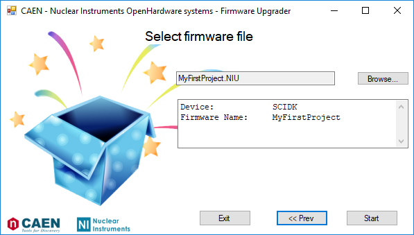
- The following window will open. Select SciDK-DT1260 from drop-down menu and press Next. Then select the PID of the board to be programmed and press Next. If no PID appears in the drop-down menu, please check USB connectivity and drivers.
- Browse your PC to the .niu firmware path, press Start and wait for the end of the process.
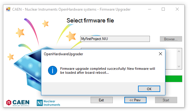
- When the process is finished, the following message will appear. Press Ok.
-
Disconnect the DT1260 unit from USB to power it OFF, move the bootloader switch to normal operation position (left hand-side) and reconnect the board again. After a while you should see the BL LED blinking in blue, telling that the board is correctly running a valid firmware.
-
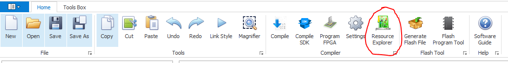
In Sci-Compiler, open the Resource Explorer
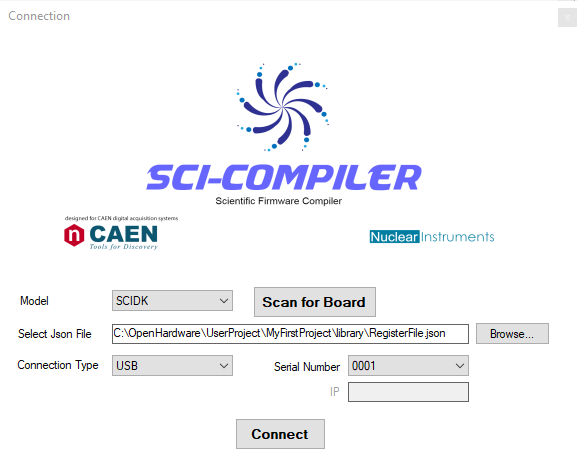
- Check that the DT1260 unit is correctly connected to the PC via USB. Select DT1260 model from the drop-down menu and choose the correct SerialNumber/PID among the ones listed. Press Connect.
- The Resource Explorer window opens and enumerates the Memory Mapped Peripheral available for the firmware installed on the board. Right click on the Oscilloscope_0 and select View.
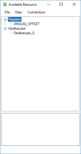
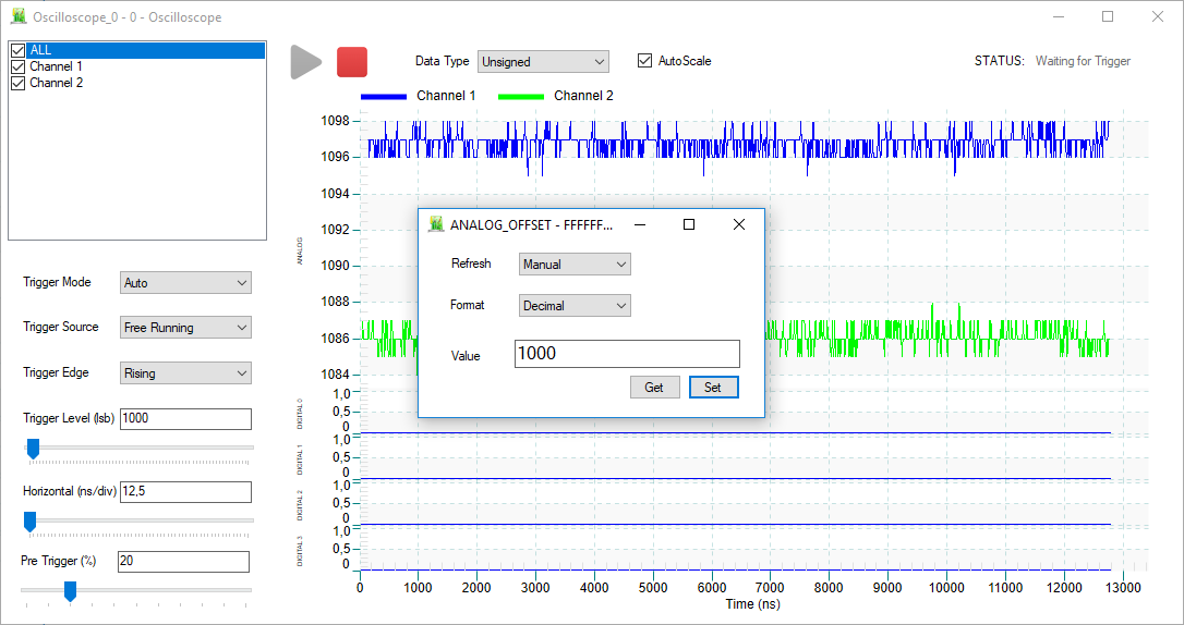
- Configure the settings as shown in the figure below, then press Play. Be careful to select free running as Trigger Source because there is no input signal connected to the DT1260 unit. You should see the baseline of the two analog input channels (blue and green traces).
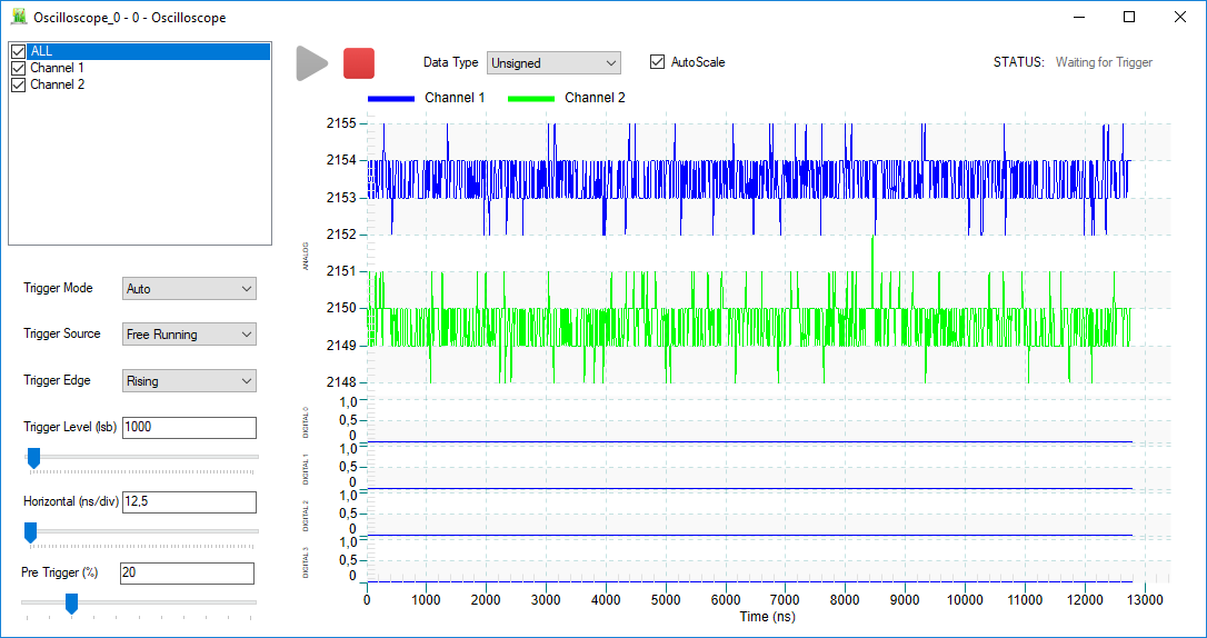
- In the Resource Explorer right click on ANALOG_OFFSET REGISTER and select Set/Get. Enter 1000 in Decimal mode, as shown below. Then press Set. In this way you have accessed the input offset register and set it to 1000, which means shifting the input channels baseline at nearly 1000 levels of the dynamic range (over a total of 4k)

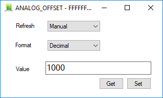
- After pressing Set, in the Resource Explorer plot, it is possible to see the two baseline traces shifted by nearly 1000 levels of the input dynamic range.